Digital material culture
yuval basteker
Computer Controlled Cutting


Assignment 1 - Experiments and Joints

power- 85 unchanged
speed- Between 5 to 80
Testing the effect on cutting toughness as a function of speed
joinery number 1


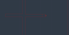
power- 85
speed- 30
Material thickness is 0.4 meter
In order to connect the two parts, I must subtract from each object a space that will allow the entry of the second joinery. In addition, the machine also subtracts material, I calculated that the material subtraction is 1 millimeter. I planned the cores of the material with a thickness of 0.3 so that in practice the result would be 0.4 and the connectors would fit exactly into each other.The result that was discovered is that the machine does not subtract 1 millimeter but less. Therefore the parts did not match each other.
joinery number 2
first attempt

Cutting the frame:
power- 85
speed- 30
Cutting of the gap:
power- 10
speed- 8
The joinery did not work as planned because the gap was too large and the gap needs to be a stamp in the thickness of the material. The gap was designed for a gap of 4 millimeters.
second attempt


After understanding the cause of the problem, the drawing of the gap was changed from 4 millimeters to 3.5 millimeters. After the change - the joinery works
joinery number 3
first attempt

power- 85
speed- 30
In order for a joinery to connect the 2 parts. It should be a little bigger, because of the material that was subtracted from the two parts and creates a larger space than shown in the drawing. The joinery I created is 1 millimeter larger than the gap created in the parts.
the joinery came out too big and therefore did not fit into the parts.


second attempt
Therefore, instead of the connector being drawn 1 millimeter more, I changed it to be 0.5 millimeter more than the gap in the parts.
The change led to joinery working.
Assignment 2 - 2D to 3D

I took a 3D model of a robot from the internet in 3dm format and put it to the appropriate scale and then put it into the plane object software.
Through the software I selected the desired number of layers and the software disassembled the model into the appropriate number of parts. I transferred the drawings of the parts to AutoCAD in order to prepare the file for cutting. After cutting, I assembled and connected according to the numbering that the software gave to each part.


The final result :

in process....
You can see the cutting settings screen - speed and power.

During the following exercise I learned to use the plane object software.
Using the software is not easy since the software tends to divide into a lot of parts, the division is not always done accurately, therefore there are corrections that need to be made in AutoCAD before moving to cutting. As a result, the resulting model is not as accurate as the Rhino model. Since there were parts that needed to be cut together and the software disassembled them into separate parts. Therefore, the division of the parts must be carefully checked and in addition there is a need for a space between the parts in order to achieve the optimal cutting of each part.
Final Assignment - Kerfing +joints


The final result :
I chose to use the Kerfing method in combination with the joints we learned in the first lesson. First, I drew a box with the dimensions I want and combined it with parts made by using the Kerfing method(a number of cuts made relatively densely) that allow the wood to be flexible for the parts in the box that need to be folded.
After I created the connection point (joints) when I took into account the thickness of the material so that the parts fit exactly into each other.


in process....
You can see the cutting settings screen - speed and power.
For decoration I have defined different definitions since engraving is necessary and not cutting.
conclusions:
1) The greater the distance between the lines, the less flexible the wood will be, but a distance that is too small may cause excessive wear of the material, so you need to find the appropriate ratio for the desired level of flexibility.
2)In order to achieve an accurate connection of the joints, I had to correct the drawing several times. In addition, several changes were made to the length of the top part so that it would cover the box exactly (the first time the top part was too long and did not fit the box)